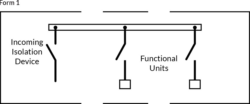
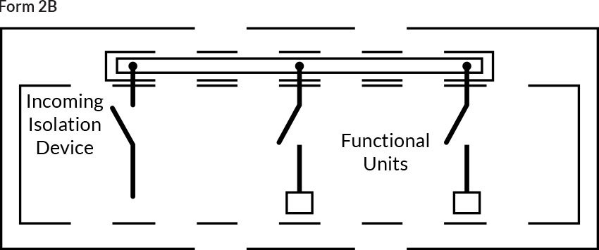
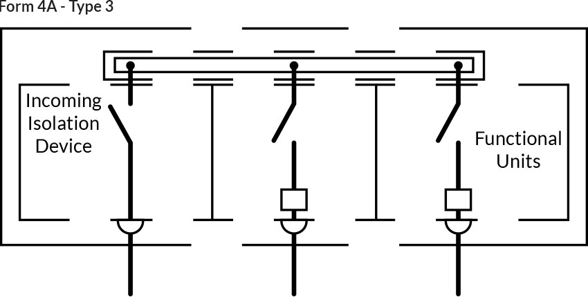
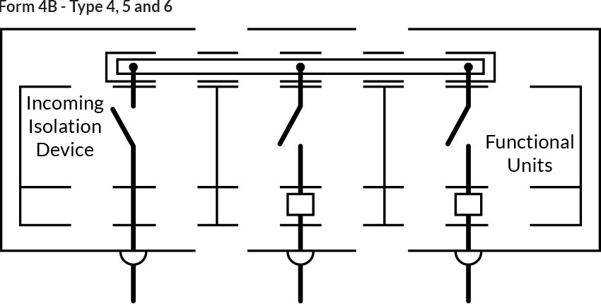
EN61439-2 refers to the 'Internal separation of ASSEMBLIES by barriers, or partitions', Table 104. This clause concerns methods of separating busbars and 'functional units' from one another when installing electrical control systems. This can be done by fitting barriers between the units, or by mounting them in separate compartments.

Click a form of separation for the guide classifications:
No separation.

Note: These forms of separation are not relevant to arc fault containment which is not the subject of this specification, and would be subject to agreement between the manufacturer, and the client.
* This information is correct at the time of this publication. Sandford Electrical Services Ltd cannot be held responsible for any changes that occur. It is the responsibility of the user to check with the relevant standard at the time of use.
Separation of the busbars from the functional units, with terminals for external conductors not separated from the busbars.

Separation of the busbars from the functional units, with terminals for external conductors separated from the busbars.

* This information is correct at the time of this publication. Sandford Electrical Services Ltd cannot be held responsible for any changes that occur. It is the responsibility of the user to check with the relevant standard at the time of use.
Separation of busbars from the functional units, and separation of all functional units from one another. Separation of the terminals, for external conductors, from the functional units, but not from each other. Terminals for external conductors not separated from busbars.

Separation of busbars from the functional units, and separation of all functional units from one another. Separation of the terminals, for external conductors, from the functional units, but not from each other. Terminals for external conductors separated from busbars.

Note: These forms of separation are not relevant to arc fault containment which is not the subject of this specification, and would be subject to agreement between the manufacturer, and the client.
* This information is correct at the time of this publication. Sandford Electrical Services Ltd cannot be held responsible for any changes that occur. It is the responsibility of the user to check with the relevant standard at the time of use.
Separation of busbars from the functional units, and separation of all functional units from one another, including the terminals for external conductors which are an integral part of the functional unit.
Terminals for external conductors located in the same compartment as the associated functional unit. Busbar separation is achieved by insulated coverings, eg. Sleeving, wrapping or coatings. Cables may be glanded elsewhere.
Terminals for external conductors located in the same compartment as the associated functional unit. Busbar separation is achieved by metallic, or non-metallic, rigid barriers, or partitions. Cables may be glanded elsewhere.

Terminals for external conductors located in the same compartment as the associated functional unit. Busbar separation is achieved metallic or non metallic rigid barriers or partitions. The termination for each functional unit has its own integral glanding facility.

Terminals for external conductors not located in the same compartment as the associated functional unit, but in individual, separate, enclosed protected spaces, or compartments. Busbar separation is achieved by insulated coverings (See Clause 8.4.2.2 of BS EN61439 Part 1 in relation to protection against contact with live parts.), eg. Sleeving, wrapping or coatings. Cables may be glanded elsewhere.
Terminals for external conductors not located in the same compartment as the associated functional unit, but in individual, separate, enclosed protected spaces, or compartments. Busbar separation is achieved by metallic, or non-metallic, rigid barriers, or partitions. Terminals may be separated by insulated covering(s), and glanded in common cabling chamber(s).
Terminals for external conductors not located in the same compartment as the associated functional unit, but in individual, separate, enclosed protected spaces, or compartments. All separation is by metallic or non-metallic, rigid barriers, or partitions. Cables are glanded in common cabling chamber(s).

Terminals for external conductors not located in the same compartment as the associated functional unit, but in individual separate, enclosed protected spaces, or compartments. All separation is by metallic, or non-metallic, rigid barriers, or partitions. The termination for each functional unit has its own integral glanding facility.

* This information is correct at the time of this publication. Sandford Electrical Services Ltd cannot be held responsible for any changes that occur. It is the responsibility of the user to check with the relevant standard at the time of use.